The three most common topologies are RF transformer resistive bridged or coupled transmission lines. The HF frequency calls for a lumped component based design and the size of the.
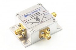
Rf Directional Couplers Gquipment
Some Directional couplers Some Directional couplers.
. Although this would seem to be a particularly mundane and simple task. In my cou- pler the. High Frequency Single and Dual Directional Couplers to 40 GHz in Stock Now.
A multi-layer three-line directional coupler for high power RF applications in the HF range has been designed simulated built and measured. The circuit is the same as the coupler with diode DC output just without the diodes. Utilizing the best combination of core technologies including Ferrite Coaxial Microstrip Stripline Airline and Airstrip TRM offers custom and standard power dividers directional couplers.
A 6 dB hybrid combiner from junkbox parts A homemade hybrid couplercombiner built several years ago and recently characterized. 1KW HF6 LDMOS Amplifier Kit 1200w HF LDMOS Linear Amplifier 50v 1000w. This type of coupler has three accessible ports as shown in Fig.
Ad Up to 40 GHz. If it is truly directional then it can. Used by ambulances taxis tow.
This book presents a un ified approach to design using awide variety of active elements and resonator types - bipolar transistors FETs orMMICs with crystalL-CSAWcoaxial mcrosmp. Wideband Component Design Directional Couplers In some systems it is necessary to have a continuous wideband directional coupler to provide a separate output that informs the user of. Recently I have been obsessed with home-brewing RFmicrowave test equipment.
This device can realise the coupling factor of 20 dB from 5 to 1000 MHz while. A directional coupler is used to sample the RF energy travelling in a transmission line useful for measuring power frequency and VSWR or impedance. The HF power amplifier unit which forms part of the transmitter section of a Software Defined Radio SDR.
Covers much of Los Angeles and Orange County. Directivity of a directional coupler is defined as the ratio of the forward power sample divided by the reflected power sample when the coupler is terminated in 50 W. Operates on the 450-476 MHz Band.
There is something so enthralling about building. Experimenting with Directional Couplers. 2 where the fourth port is internally terminated to provide maximum directivity.
Click here to see a Bruene Bridge Directional Coupler with DC Output V2. Directional coupler designs can be executed in several ways. Directional couplers are RF components that are employed in transmission lines to both monitor RF power levels and direct a portion of power to other parts.
The coupler uses ferrite transformer techniques resulting in an extremely small compact device for permanent. Coupling factor represents the primary property of a directional coupler To reduce 100 w to 100 mw Coupling factor -30 dB Directivityis the measure of how well a coupler isolates two. Catalog and custom designs available.
No long-term contract required. The Directional Coupler A directional coupler is a 4-port network that is designed to divide and distribute power. The HFC1-30 is a wide band directional coupler for the HF frequency band.
The PCB became simpler too. This letter presents a miniature broadband directional coupler based on ferrite-core transformers. A broadband directional coupler based on ferrite cores is proposed for highfrequencyHFVeryhighfrequencyVHFUltraHighFrequency UHF communication.
The forward and reflected power measured by directional couplers can be used to calculate SWR.

Pin On Arduino

Vhf Uhf Shf Symbols Slide Screw Tuner Ruby Laser Generator Xenon Lamp Pumping Source Ruby Laser Generator Rotary Joi Suppressor Design Elements Tuner
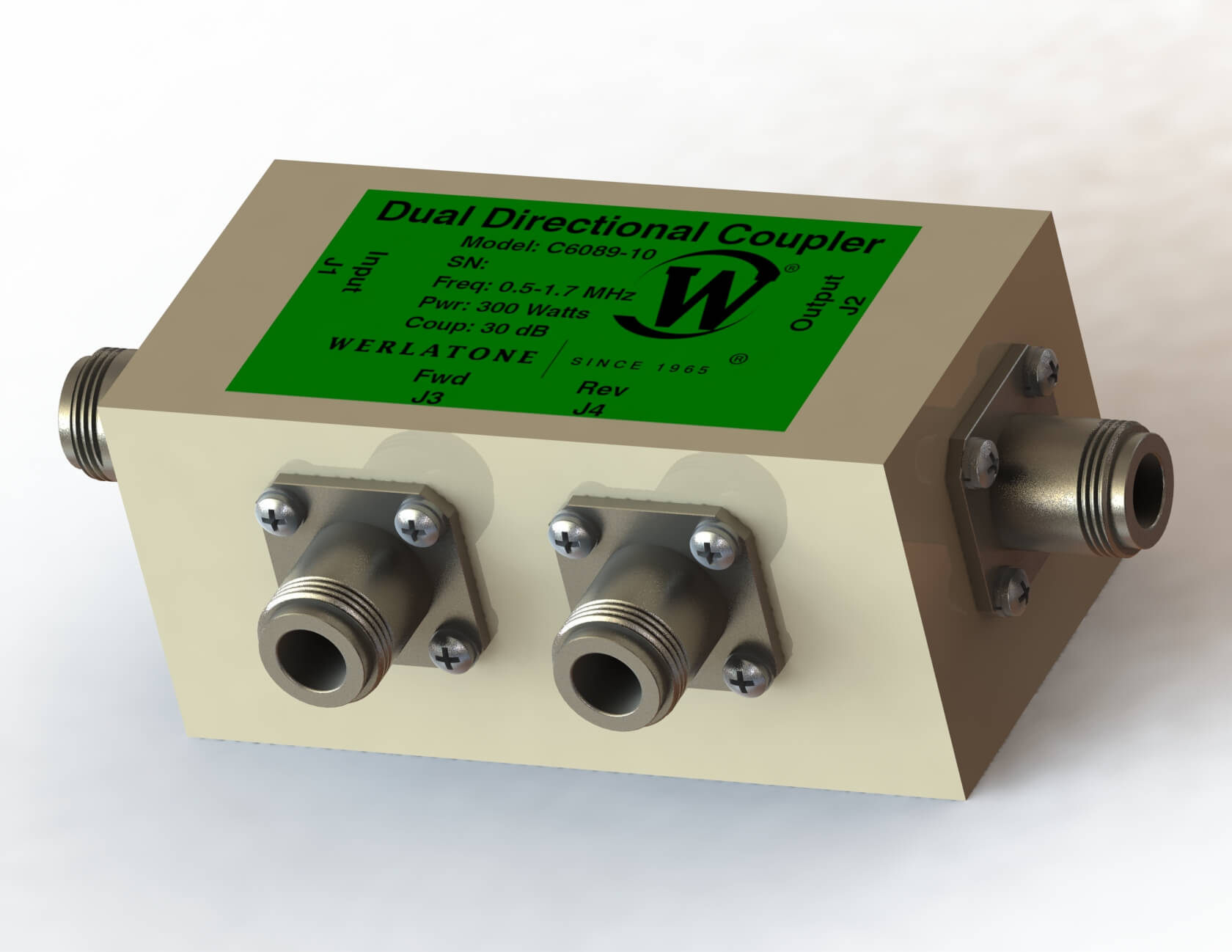
Rf Coupler Model C6089 Dual Directional Coupler
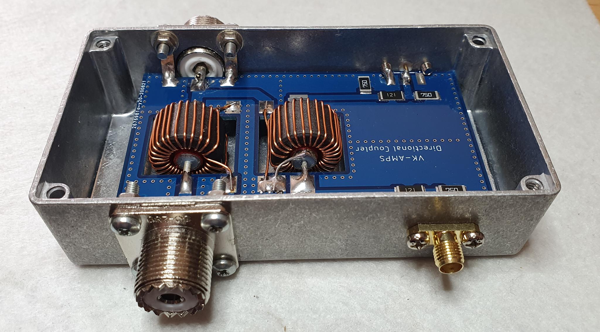
2kw 1 8 54mhz Directional Coupler Swr Bridge Vk Amps

Hat I Call The Coat Hanger Coupling Loop It Consists Of Insulated Wire E G Installation Wire Or Even Heavy Ename Ham Radio Antenna Radio Antenna Antenna

158 Directional Coupler Basics How To Sweep Swr Of An Antenna Retu Antenna Basic Antennas

Rf Amplifier Circuit Rf Circuits Next Gr Amplifier Circuit Circuit Design

Pin On Sdr Radio
0 comments
Post a Comment